I was recently given a few inexpensive Honda battery sensors for free. These sensors are known as IBS (Intelligent Battery Sensor) or EBS (Electronic Battery Sensor) and are commonly used by vehicles for monitoring the condition of the battery and controlling the charging circuit to maximize battery life. I was curious to see if I could integrate them into my engine management system to record some additional data.
After some searching around the internet, I found that there was a lot of information on Hella IBSs out there, but they physically looked different from the sensors I had. Searching “Hella Honda battery sensor” did not return any results that looked promising either, so it did appear that these sensors were from a different manufacturer. Naturally, my next guess was Bosch. The Bosch EBS sensor generic information page had a photo that looked very similar to the Honda sensors I had received, and, searching “Honda Bosch battery sensor” turned up some results from parts suppliers listing Bosch as the manufacturer. Unfortunately, that is where the information stopped. When researching the Hella IBS sensor it was easy to find two GitHub repositories containing libraries to read data from these sensors, such as IBS-Sensor-Library and IBS-Sensor-Lite, but, no such information or discussion existed for the Bosch sensors.
Given that I received these sensors for free and could find cheap no-brand replacements on Amazon for less than $50 I decided to give reverse engineering them a shot.
If you’re just interested in the final result and not the process, skip to the end now!
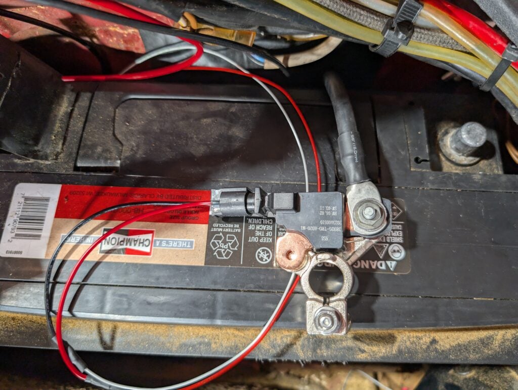
Given that these sensors sit on the battery negative terminal and have only two other pins to interface, it was a pretty safe assumption that one pin is power and one pin is a single-wire communication bus, most likely LIN. Googling for wiring diagrams/pinouts confirmed that. I was able to find the following diagram from a forum post about CRV alternator issue diagnostics:

From higher in the diagram it was clear pin one was switched 12V and pin two is connected to a shared LIN bus between the ECU and alternator.
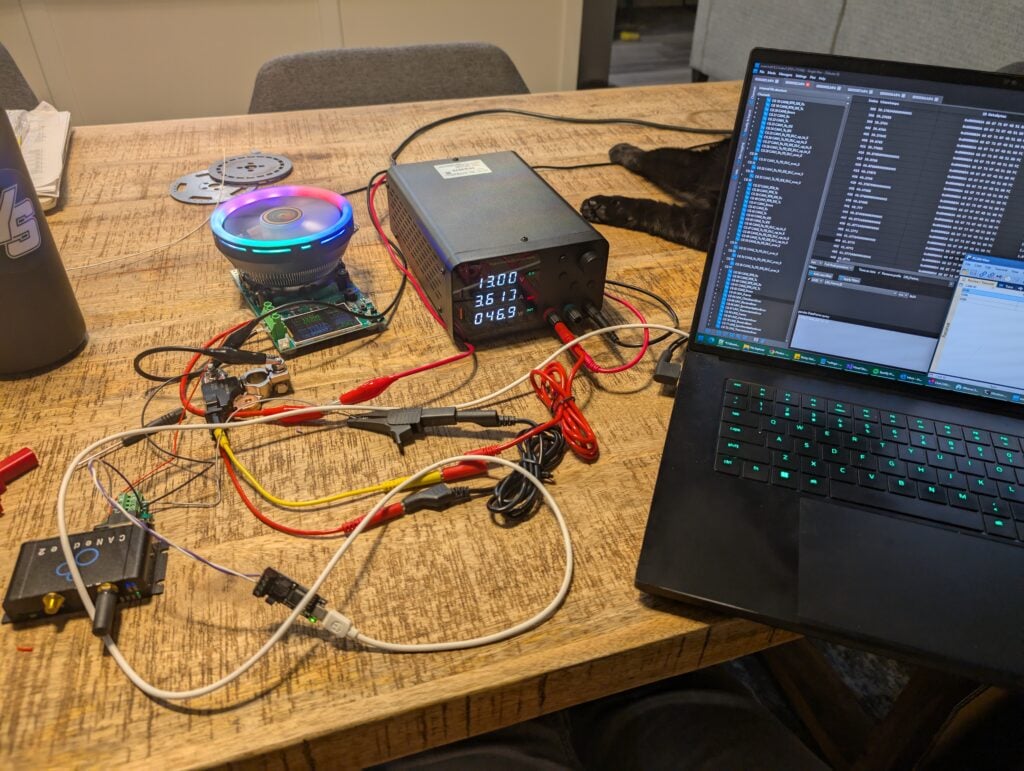
To begin the reverse engineer process, I grabbed one of the cheap benchtop power supplies I had sitting around the house, a digital load current sinking device from the office, and a CANEdge2 CAN/LIN logger I was using in my car to log data and send GNSS (GPS)/IMU data to the CAN bus.
The sensors I had received did not come with a connector and there was no pin numbering printed on them. Finding a visual pinout was not possible online. Given that LIN is a 12v bus, it seemed safe enough to just try powering both pins until the unit began drawing current. On my second attempt I had the pins oriented properly and from the load displayed on the benchtop power supply it was clear the sensor had powered up.
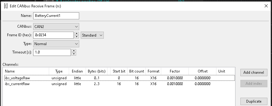
To start trying to receive data from the sensor, I wired it to the LIN input on the CanEdge2 and hopped into the configuration editor. For those unfamiliar with LIN, it is a bit different from CAN in that there is one master that controls the messages sent on the bus. The master can broadcast a message asking for data at a certain address, and a listening node can then respond with the data if the address matches. The master must also know how many bytes of data will be sent by the listening node. Because of these features, reverse engineering is a bit more tricky. The address of the device you wish to interact with must be determined ahead of time.
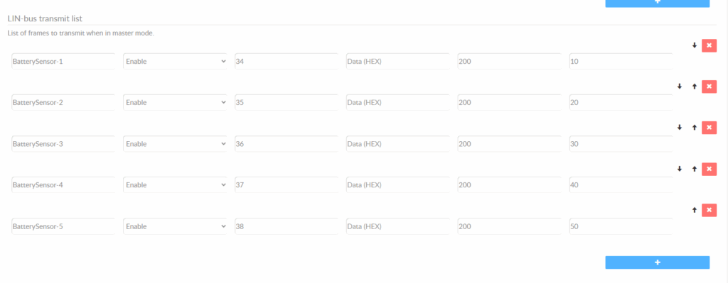
To find the ID, I would configure the CANEdge2 to request data at every address on the LIN bus in small batches. If there was no response, an error would be logged. If a response was received that did not match the data size expected, an error would be received as well. If the addresses and data size matched up, the data would be logged.
LIN luckily only officially supports 63 address (0x00 – 0x3F), and it only took me until 0x34 to start receiving some data. The device ended up sending data on 0x34-0x38 and I polled at an interval of 200ms.
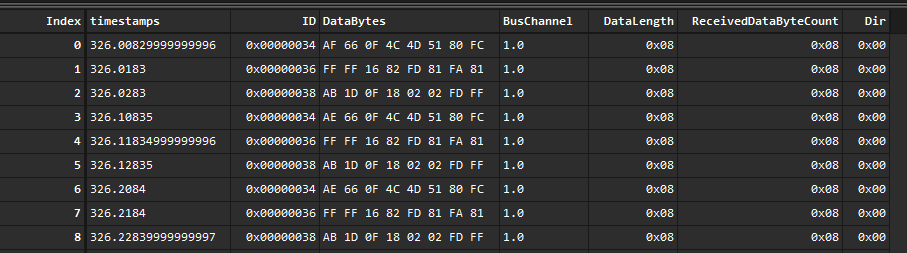
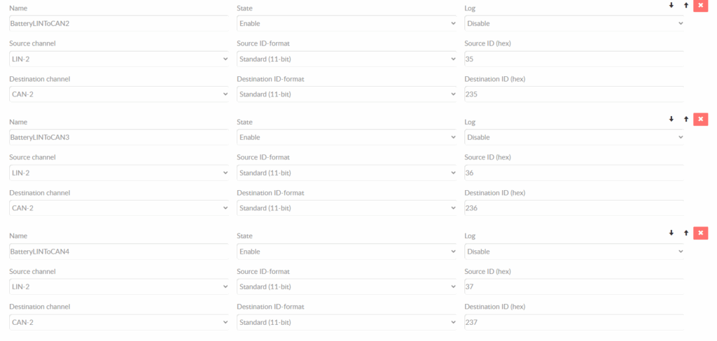
To speed up the process, I configured the CanEdge2 to rebroadcast those messages over the CAN2 bus and connected to the bus with a live data logger on my laptop.
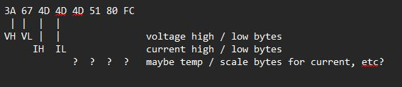
I began playing with the current pulled by the digital load tester and voltage supplied by the PSU and watching the live data. The only address with changing responses was the first, 0x34. The first two bytes contained what appeared to be voltage and the second current.
I decided to focus on current at first and was left scratching my head to some strange values. Eventually, I decided to just convert the little endian hex values to decimal and plot them in Excel. It appears that the sensor switches to a second curve while reading between -1 and 1A of current. Given the slope is less, perhaps it is for a more accurate reading in this low current range? What is strange however is that the voltage also switches to a different curve in this region, however the slope is the same but it has a different offset.

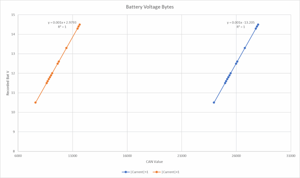
Not sure what that is about, but the R^2 values of the excel linear fits seemed plenty good enough for me to be happy with these values to continue testing.
Using my benchtop power supply and digital load tester I could not get any changes in the other data frames being sent over the bus. Bosch does claim that this sensor should read battery temperature as well, so I will work on that next. From my reading of the Hella reverse engineering efforts I also know that those sensors have a calibration period where they learn the battery behavior and then start sending age and health data to the bus. Those currently static frames could very well contain that information.
Using roughly those formulas I went ahead and installed the CanEdge2 back into my car with the IBS. One of my cheapo sensors came with a flying lead cable so for initial testing I used that. The connector appears to be a (likely knock-off) TE with part number 968405-1. TE did not have any information on their website of this connector, only a -2 variant which was out of stock and of low informative value. I will continue to do research and see if there is a new part number that will work for these as well as find the contact part numbers.
Everything seems to work!
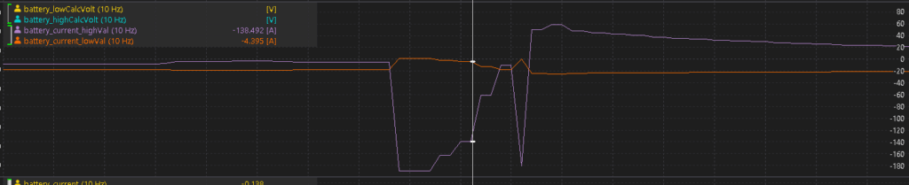
Here is a log snapshot from cranking and starting the engine. The IBS reads ~-3/-5A while I am sitting in the car with the engine management and accessories running. My first crank attempt pulls about 180A on the battery and fails. A second crank attempt pulls a bit less but the engine fires right away. The battery begins taking a strong charge at around 48A which quickly subsides down to 3A later in the log. After my drive to work with the car idling the sensor was reading around 1A of current into the battery.
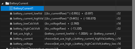
My ECU (ECUMaster EMU Pro 16) allows me to define custom CAN messages, numbers, and functions. To read voltage and current from this sensor in a single channel I set up a few calculation and logic channels which ended up looking like this:
I will continue to update this page as I spend more time reverse engineering this sensor with data from a real battery and vehicle. I will upload some LIN logs of all of the frames as well after I have a week or so of data collection.
Here is a summary of all of the information I have learned so far:
| LIN bitrate | 19200 |
| LIN message addresses | 0x34, 0x35, 0x36, 0x37, 0x38 |
| Pinout | 1 – 12V switched; 2 – LIN |
| Battery current bytes | 0x34 0 and 1 (little endian) |
| Battery voltage bytes | 0x34 2 and 3 (little endian) |
| Battery voltage translation | If |current| < 1A: 0.001 * value + ~3 If |current| > 1A: 0.001 * value – ~13 |
| Battery current translation | If |current| < 1A: -0.001 * value + ~0.9 If |current| > 1A: 0.0094 * value – ~189 |
| Connector PN | TE 968405-1 |
| Used in models | Honda CRV (early 2010s) Honda Civic (early 2010s) Acura ILX (mid-late 2010s) Acura RDX (mid-late 2010s) Possibly some FCA vehicles (Cherokee, RAM, Charger) – not sure if data format is the same but sensor appearance definitely is |